
We have already discussed about main scenarios (eMBB, mMTC, uRLLC) and key performance targets need to be achieved in 5G and how 5G is different from 4G in the previous article. The advanced New Radio technologies are mainly designed to achieve the key performance targets for each of the main scenario. If you don’t have understanding about these concepts, follow this link to understand the concept of 5G main scenarios and key performance targets.
Advanced radio technologies are adapted in 5G to achieve key performance targets; higher bandwidths for high peak throughputs and user experience throughputs, advanced multiples access technologies, advanced filters, massive MIMO, advanced channel coding and modulation for higher spectral efficiency, flexible resources like flexible slot, flexible subcarriers spacing (SCS) to make possible use of mmWave frequencies and lower latency/ higher throughputs for difference scenarios like eMBB, mMTC and uRLLC.What is 5G NR Frequency Spectrum?
In 3GPP TS 38.104 section 5.2, NR operating frequency bands are defined. You can see 3GPP release 15 defined frequency bands in here. In 3GPP release 15, these 5G frequency bands are categorized into two Frequency Ranges (FR), FR1 and FR2.

These bands can be further categorized into three categories.
2. Time Division Duplex bands (TDD)
3. Supplementary Bands: Downlink Supplement band (SDL) & Uplink Supplement band (SUL)
Supplementary bands are designed for uplink and downlink decoupling function. I will discuss about this topic in a separate article.
Currently, the major band for 5G deployment is C-band which includes n77, n78 and n79.

In release 15, only four FR2 (milli meter Wave - mmWave) frequency bands are defined.

There are certain advantages and disadvantages of using different frequency bands. Let’s discuss about these in detail.
- Sub-3G Band: Sub-3G band is referred to the frequency bands below 3 GHz. Problem in these bands for 5G is that there bands are already allocated for various applications and technologies; 2G, 3G, 4G and Other wireless applications. Therefore finding considerably large bandwidth in these bands is not possible; which is one of main requirement to achieve higher 5G data throughput. But these bands have the advantages of having lower propagation and penetration losses which ultimately provides better uplink and downlink coverage. Because of that 3GPP defines some of these bands are as supplement bands for uplink and downlink decoupling; to cope with UL/DL imbalance and achieve better coverage.
- C-band: C-band is ranging from 3.4 GHz up to ~7 GHz frequencies. This is currently the major band for 5G deployments. 3GPP defines three main bands within the C-band: n77, n78 and n79. Availability of higher bandwidths like 50 MHz, 100 MHz per network in these bands will enable high capacity and low latency requirements which are ideal for 5G use cases such as eMBB, uRLLC etc. These mid bands will provide reasonably better coverage, capacity, throughput, quality and low-latency performances; therefore become most popular bands for 5G deployments.
- mmWave bands: these high bands will provide high capacity, high throughput, high quality and low latency performances for 5G. Continuous bandwidths of more than 100 MHz per network are possible in these bands. These bands will enable eMBB for hotspots, low latency applications. But these higher bands have certain disadvantages due to high frequency. They are absorbed easily by air gases, trees, buildings and other obstacles. Therefore high path loss and high penetration loss will result in lower coverage. But other than above mentioned advantages and disadvantages, high reflection and diffraction characteristics of these waves will help for multi path reception at the UE side and obtaining higher MIMO ranks and therefore achieving higher user data throughputs.
There is a tight interworking between 4G and 5G at least at the early development and deployment of 5G. In Non-Standalone (NSA) deployments, eNodeB functions as control plane/ user plane anchor for 5G.
But many features are exclusive to NR compared to 4G, such as its variety of use cases, deployment scenarios ranging from low coverage to high coverage over the conventional 4G mobile broadband.
5G Waveform/ Multiple Access Technologies
- Uses F-OFDM (Filter Orthogonal Frequency Division Multiplexing) which adopts advanced filtering techniques; controlling the outside band emissions and receptions. Therefore F-OFDM will provide 5G a lower Guard band between carriers, higher usable bandwidth for effective use and increase the spectral efficiency.
- In 5G uplink, both the CP-OFDM and DFT-S-OFDM (SC-FDMA) are used adaptively based on uplink signal quality.

If you want to learn basics of OFDM, refer this article by electronicsnotes.com.
In addition to what we discussed, there are other potential waveforms/ multiple access schemes have been introduced for different requirements and use cases; this standardization is not finalized yet. As an example, to meet the requirement of high connection density of mMTC, non-orthogonal multiple access (NOMA) techniques are proposed. Sparse code multiple access (SCMA) is another candidate access methodology which successfully combines OFDMA and CDMA and provide high user capacity and higher spectral efficiency. And there are multiple access methodologies considered which I am not going to discuss in here as this area of standards is not frozen yet.
Numerologies and Frame Structure
5G defines flexible numerologies in 3GPP TS 38.211 as indicated in below table. Numerology is defined by sub-carrier spacing and CP overhead.
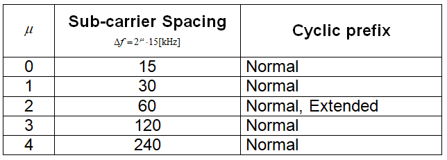
240 kHz sub-carrier spacing is used for sending downlink synchronization signals and following table lists the different frequency band supporting sub-carrier spacing.


Following picture depicts slot arrangement of a subframe for different sub-carrier spacing.

Downlink Slots: All symbols in a slot are downlink.
Uplink Slots: All symbols in a slot are uplink
Flexible Slots: All symbols in a slot are flexible. Flexible slots can be used in uplink or downlink transmission.
Mixed Slots (Self-contained slot): Mixed slot contains at least one DL symbol and one UL symbol and other symbols can be flexible. 3GPP doesn’t clearly define this type of slots and self-contained slots are designed for the purpose of shortening the RTT for specific applications.
In 3GPP 38.213 11.1, different slot formats are defined. Format 0 indicates downlink slot and format 1 indicates uplink slot. And other formats (format 2 -55) support flexible slot configurations. Follow this link to see full list of formats.

Time Slot Ratio Parameter Configuration
Mainly five parameters are used to configure time slot ratio of 5G. Time slot ratio defines how the downlink, uplink and self-contained slots are arranged within defined period.
- Period (x/y): Period implies the time period that we consider for defining slot ratio parameters. 0.625ms is only for 120 kHz SCS, 1.25ms is for SCS>= 60 kHz, 2.5ms is used for SCS >= 30 kHz.
- Number of downlink slots (x1/x3): defines number of downlink slots within the period.
- Number of downlink slots (y1/y3): defines number of uplink slots within the period.
- Number of downlink symbols in special slot (x2/x4): defines the number of downlink symbol in the special slot which is self-contain slot lays between uplink and downlink slots.
- Number of downlink symbols in special slot (y2/y4): defines the number of uplink symbol in the special slot which is a self-contain slot lies between uplink and downlink slots.
Y, x3, y3, x4 and y4 are used only in dual period configuration.
Example single period configuration 4: 1 (DDDSU)

5G introduces higher modulation orders to achieve higher spectral efficiency. In 3GPP release 15, the maximum modulation in the downlink is introduced as 256QAM. But in the next releases 1024QAM will be introduced and further enhance the spectral efficiency. And in the uplink 256QAM is newly introduced.
Downlink : QPSK, 16QAM, 64QAM, 256QAM, 1024QAM (not defined in release 15)
Uplink: QPSK, 16QAM, 64QAM, 256QAM
Channel Coding for Higher Spectral Efficiency
In 5G mainly two channel coding methods are used.
- LDPC (Low Density Parity Check Code) for eMBB Data Channel
- Polar Code for Control Channel
For uRLLC and mMTC, channel coding methods are not finalized yet.
NR Massive MIMO
These static beams can be planned and configured (weights, azimuths, tilts etc.) based on user distribution in horizontal and vertical planes and mainly used to carry control and broadcast traffic.
 Dynamic beams are adjusted based on user distribution in the 5G coverage area and user traffic demand for each user which enhances the efficient use of radio resources.
I will discuss this topic in detail with another article. Following are some characteristics of beams use for traffic and control channels.
Traffic
Channel
|
Broadcast
Channel
|
· High gain
narrow beam
|
· High gain
narrow beam
|
· Dynamic
adjustment of the beam forming direction
|
· Beam scanning
with predefined directions
|
· UE performs beam scanning to get the best broadcast
beam
|
I will do some articles with my available time on some of NR key technologies in detail for the people whom interested in learning about 5G NR technologies in depth.
Keep in touch!!
Here is a good article by qualcomm about 5G NR.
Thank you for content. I like it and my site is different for your site. please visit my site. คาสิโนออนไลน์
ReplyDelete